WIPER MOTOR AND COMPONENTS
The best wiper components are found in the 1969-1976 Triumph Spitfire, GT-6, or TR-6. Get the entire set-up including: wiper motor, wheel boxes, spacers, gaskets, chrome bezels, and the connecting tube between the wiper motor and right wheel box. See the wiper motor illustrations on page 42 to help you identify the parts.
Many times, the wheel-boxes available are not correct. Measure across the teeth of your gear to the theoretical center of the cable. (Some of the gears are flat, some are concave.) If your dimension is 1.45", not 1.25", the wiper drive must be modified to compensate. See page below for details.
OVERVIEW OF MODIFICATIONS
The original-style Lucas wiper motor and drive uses a spiral-wound drive cable that engages gears at each wiper arm. By driving the cable back and forth in a rigid housing, the gears and wiper arms rotate. The amount of rotation is determined by the stroke of the drive cable and the diameter of the wheelbox gears.A switch in the motor that remains closed during 350 degrees of the rotation of the drive gear, automatically parks the wiper arms on the right side of the windshield after the dash switch is shut off. Some motors have the switch cam oriented incorrectly. Check the section below for the correct orientation
Unfortunately, the best wheel boxes (listed in Section A) are rarely available. If your wheelboxes do not match the specifications on page 16, the crankshaft in the wiper motor may be modified to compensate. See Stroke Changes below.
MOTOR PREPARATION
If you are sure that the wiper motor functions correctly and don't want to disassemble the wiper motor itself, skip steps 4 through 8.
- Take out the 4 screws holding the cover to the gearbox, and remove the cover.
- Remove the circlip and washer from the connecting rod big end, and remove the connecting rod. Note the bottom washer.
- Remove the circlip and washer from the back side of the crankshaft, and push out the crankshaft from the housing. Retain all the parts! Note the thrust washer on the inside of the crankpin.
- Mark the relative position of the round motor housing to the aluminum gear reduction housing. Remove the two long screws holding the motor housing to the frame. Separate the two (with gentle soft hammer taps if necessary). Do not lose the felt washer and thrust washer in the bearing cup at the bottom of the housing.
- Inspect the brushes for wear or sticking, the commutator for excess wear and arcing, and the lower bearing. Clean the parts with a solvent if necessary. Work the brushes in and out to insure free motion.
- Install the armature carefully into the gear housing until it contacts the sides of the brushes. Using a hook shaped wire or other appropriate tool, retract each brush in turn so that the commutator can slide past the edges of both brushes and continue into the gear case
- Put 1 or 2 drops of oil in the lower bearing of the armature housing. Excess oil will contaminate the brushes later on.
- Install the armature housing, aligning the marks on the housing and the frame. Reinstall the long retaining screws.
STROKE CHANGES
Remove the plastic gear from the crankshaft by supporting the edge of the gear and tapping the shaft with a soft hammer. Be careful not to damage the circlip groove.
The position of the crankpin must be changed in order to increase the stroke of the cable: Punch the underside of the crank plate exactly opposite the center of the crankpin. Use a 3/8" Blair spotweld cutter to cut the pin from the plate, drilling from the back side at the punch mark. The pin will be removed, together with a small piece of the plate.
Drill a 17/64" hole in the opposite side of the crankplate at the position indicated in the illustration. Countersink from the crankpin side just enough that the crankpin will be flat on the plate after insertion into the hole.Weld or braze the pin in the new hole from the back. Clean and deburr the crankshaft.
Install the plastic gear onto the crankshaft, engaging the tangs of the gear into the crankshaft notches. Note that the plastic cam is adjacent to the crankpin.
Grease the shaft lightly, install the conical thrust washer, and insert it into the housing. Install the outer thrust washer and circlip.
Partially fill the gear housing with grease, and place the cable into the guide. Some guides are integral; others have separate plastic liners. Install the connecting rod with its thrust washers, and the connecting rod circlip.
Install the cover plate with 4 screws.
CHECKING THE CABLE/GEAR WHEELBOX CLEARANCE Before you install the wheelboxes, it's a good idea to check that the cable engages the gear properly. Unfortunately, the quality of the wheelboxes has not been consistent lately. Make sure that the tubes line up properly with the gear so that there is no binding, and that the cable is held close to the gear, but not so close to make excessive drag. | 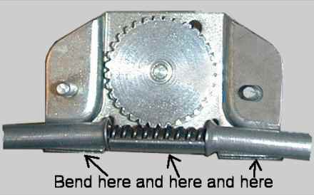 |
CONNECTING TUBES
Undo the large nut and remove the cable tube/wheelbox assembly from the motor.
Remove the wheelbox backing plates and disconnect the tubes from the wheelboxes.
Using a tubing cutter or hacksaw, cut off approximately 2 3/4" from one end of the original tube between the right wheelbox and the motor. Save the nut and the piece of tubing removed. The new tube section replaces the original end guide.
Slide the nut onto tube nearest the motor (the shorter of the two supplied and with only one end flared).
Flare the end of the tube with the nut. Slide the drive cable through the tube. If the cable is tight at the new flare, use a 1/4" drill bit to "clean" the inside of the tube.