Troubleshooting Charging Problems

ALTERNATOR AND VOLTAGE REGULATOR

OVERVIEW:

The alternator has a centrally rotating set of coils powered from the field terminal. As this rotor turns, it drags a magnetic field past the stationary coils that surround it.

This magnetic field generates alternating current within these stationary coils, which then passes through a grid of one-way valves (diodes) to produce the DC current useful to automotive applications.

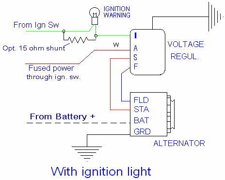
The voltage output is governed by the amount of current in the field circuit, and is controlled by the Voltage Regulator. Current is fed to the battery and other power absorbers through the large Bat terminal on the back of the alternator. A ground connection on the alternator case completes the electrical circuit. There is also a Stator terminal on the alternator, but it is not used on the 427SC. The battery power comes from a connection on the starter solenoid.

Power flows from the ignition switch, through a fuse, to the voltage regulator. Voltage is measured from this source. Internal circuits take the power source and regulate it, sending it to the field terminal of the alternator so that the output voltage to the battery is correct.
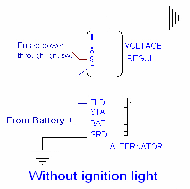
Without dash light
With ignition light

TESTING
Use the Basic Wiring Primer and Troubleshooting Guide for simple procedures for testing the alternator and regulator.
(not finished, but still very useful)

Note! A fully charged battery will show no charge under many circumstances. Check the system by turning the fan on with the engine running. You will normally see a discharge at idle that changes to a charge condition above 1500 rpm.

If this is the first time the car has run, check the polarity of the gage by turning the lights on with the ignition switch off. If the ammeter moves to the positive side, switch the wires on the ammeter.

See the wiring diagram for the appropriate fuse for the voltage regulator. Replace if necessary.

If the car shows continuous discharge, check all the connections at the alternator and voltage regulator.  Don't forget the ground wire on the voltage regulator!

Check the voltage at the Bat terminal on the alternator. If the voltage is 13.5V or more with the engine running, there is a connection problem downstream. Follow wires and/or use the wiring diagram.

If the voltage is less than 13.5V, remove the plug connector at the voltage regulator. With the ignition switch on, check that there is 11.5V minimum between the red wire and the black ground wire to the regulator case. If not, trace the red wire back to the fuse box, the black wire to its connection at a ground. Use a short wire to jump between the red and brown wires on the plug. Start the engine and slowly raise the RPMs to 1500 MAXIMUM. If the ammeter shows a charge, the problem is in the regulator.

If there is no change, the problem is in the alternator. Replace it, or better yet, bring it to a testing facility.

Sympton: Battery slowly goes dead, but ammeter sometimes shows a positive charge.

This is usually a bad diode in the alternator, less often a bad regulator. There may also be a high current draw from some components, overwhelming the alternator capacity. With the ignition switch on but the engine off, turn things on, one at a time. Check the ammeter for an indication of excessive current draw.