ERA 289FIA WHEEL
SIZES AND OFFSETS
Over the years, we've put many different size wheels
on
our FIAs. The table below shows what we have determined to fit
correctly with the tire size indicated. I can supply supply
the
wheel manufacturer with more pin-drive and bolt-on wheel hub dimensions
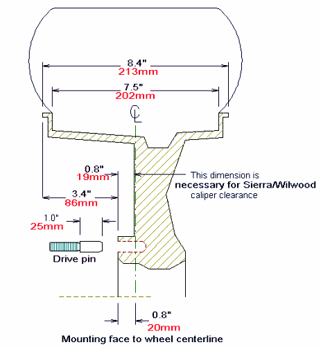
on request. For machining reference, basic drawings of the front and rear Pin-drive hubs
are here. Special notes, Drawing links, and Hints Generally,
you can calculated the offset by using 0.4" for the width of the rim
beads. So offset = (width-0.8')/2 - backspacing. (That defines
the offset as negative if the wheel moves toward the car centerline.)
FRONT
(Pin-drive and bolt-on wheel spec's are the
same)
|
Recommended Tire
Size
| Wheel
Size
| Backspacing
(See below for measuring)
|
| 225-60-15 | 6.5"W x 15" | 3.4" |
235-60-15
| 7"W x 15"
| 3.75" *Note!
|
| 235-60-15
| 7.5"W x 15"
| 3.9"
|
| 265-50-15 |
7.5"W x 15" |
3.9" |
275-50-15
| 8.0"W x 15"
| 4.3"
|
| 275-40-17 |
8.5"W x 17" |
4.9" |
Note! You
must
maintain at least 0.8" clearance for the optional 4-piston front
calipers. See the picture below.
REAR, PIN DRIVE (Jaguar and ERA rear suspension
|
Tire
Size
| Wheel
Size
| Backspacing
(See below for measuring)
|
| 275-50-15 | 8.5"W x 15" | 3.5" |
295-50-15
| 9.5"W x 15"
| 3.9"
|
| 295-50-15 | 10.0" W x 15" | 4.15" |
315-35-17
| 10.5" W x 17"
| 4.7"
|
| 315-35-17 |
11.0" W x 17" |
5.0" |
REAR,
BOLT-ON (ERA rear suspension
|
Tire
Size
| Wheel
Size
| Backspacing
(See below for measuring)
|
| 275-50-15 | 8.5"W x 15" | 3.8" |
295-50-15
| 9.5"W x 15"
| 4.1"
|
295-50-15
| 10.0" W x 15"
| 3.9"
|
315-35-17
| 10.5" W x 17"
| 5.0"
|
| 315-35-17 |
11.0" W x 17" |
5.3" |
If you need help
with this, please
e-mail
us* with the intended diameter, width and tire sizes.
*This
service is only for ERA owners.
(Tire
Size
Calculator) |


